Hardware blocked

Hardware execution blocked

No compatible nRF52840 board or supported debug probe was detected. The prerequisite check was completed, but physical deployment and measurement cannot proceed until the target hardware is connected and identified.

Board identityUNRESOLVED_NO_SUPPORTED_DEVICE_DETECTED
Detected serial interfaceLegacy COM1 only
Zephyr targetNOT_SELECTED
Physical executionNOT_EXECUTED
MemoryNOT_MEASURED
LatencyNOT_MEASURED
EnergyNOT_MEASURED

Planned hardware system

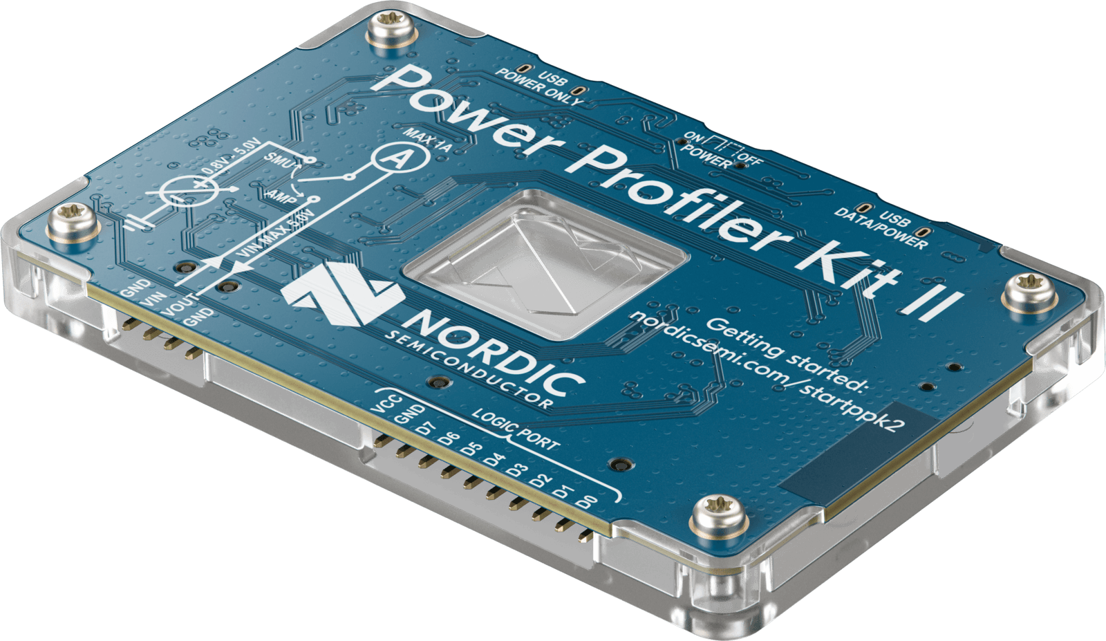
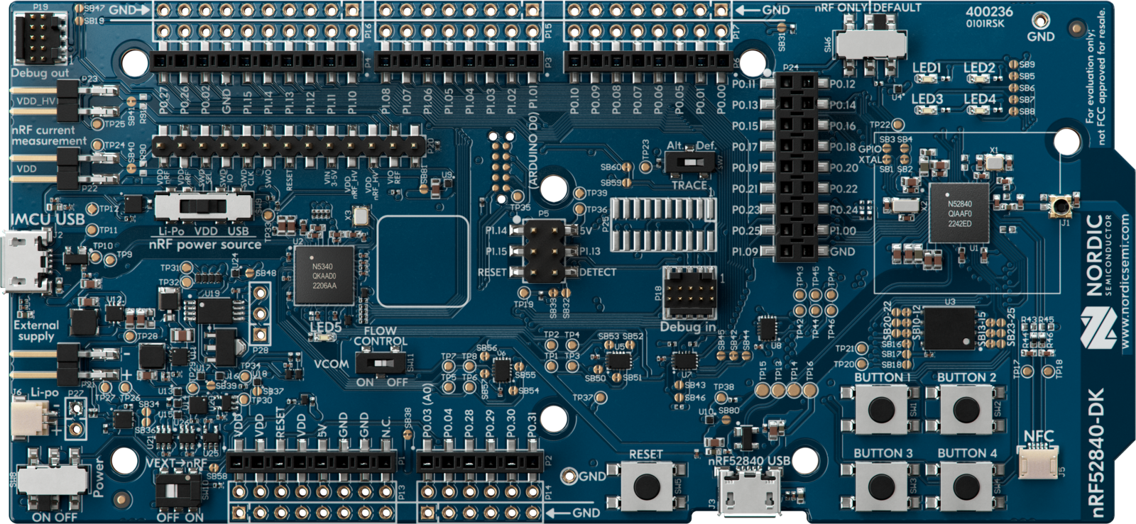
Official product photographs identify the intended equipment only. They are not evidence that the laboratory owns or has connected either device.

Planned connection

PLANNED CONNECTION — NOT PHYSICALLY EXECUTED
Planned computer, PPK2, and nRF52840 DK measurement topologyA computer connects to a Power Profiler Kit II over USB. The PPK2 planned VOUT and ground path supplies or measures an nRF52840 development kit through its dedicated measurement header. An optional GPIO trigger marks inference windows. Current traces return to the computer and are exported as files.ComputernRF Connect for DesktopPower Profiler appraw trace + exportsPower Profiler Kit IISMU or ampere modeUSB + digital inputVOUT · GND · triggernRF52840 DKP22 / SB40 pathoptional GPIO triggernormal USB power off*USBVOUT + GNDoptional GPIO markerraw current tracehardware/ppk2_logs/exported trace destination
Planned physical measurement topology. The PPK2 communicates with the Power Profiler application through USB and supplies or measures the nRF52840 DK through its dedicated current-measurement path. An optional GPIO trigger can mark inference and explanation windows. This diagram documents the proposed setup and is not evidence that physical measurement has occurred.* P22/SB40 preparation, measurement mode, and removal of normal DK USB power depend on the verified DK revision and official Nordic procedure; no board modification is instructed or recorded here.

Measurement workflow

  1. 1Model exportHost artifact available
  2. 2Firmware buildBlocked by hardware
  3. 3Board programmingBlocked by hardware
  4. 4Functional validationBlocked by hardware
  5. 5Repeated inferenceBlocked by hardware
  6. 6PPK2 trace captureBlocked by hardware
  7. 7Trigger-window extractionBlocked by hardware
  8. 8Energy integrationBlocked by hardware
  9. 9Evidence registrationBlocked by hardware
After real traces exist, inference and explanation windows will be integrated separately using E = ∫ V(t)I(t)dt. No post-detection step is shown as completed.

Measurements

No zeros, estimates, simulated values, or host-to-MCU conversions are presented.
MeasurementUnitCurrent state
Linked ROM / FlashKBNot measured
Static / peak SRAMKBNot measured
MCU inference latencymsNot measured
MCU explanation latencymsNot measured
PPK2 inference energyµJNot measured
PPK2 explanation energyµJNot measured
Linked ROM / FlashKB
Not measured
Static / peak SRAMKB
Not measured
MCU inference latencyms
Not measured
MCU explanation latencyms
Not measured
PPK2 inference energyµJ
Not measured
PPK2 explanation energyµJ
Not measured